SYSTEM DESIGN
A few general principles guided our designing a rainwater harvest system, although it must be admitted that many details were worked out as constuction proceeded.
Regulatory Issues
As of 2012, the only State, County, or Municipal regulation governing domestic rainwater collection is the requirement that any such system be separated from a public supply in such a way that unapproved water cannot siphon or leak §into the public system. While this laissez-faire policy is understandable given the rarity of the technology, it means that officials in charge of permitting and public health have no guidelines to aid them in carrying out their responsibilities. This lack had consequences in our case: Bexar County officials initially denied approval of our septic system permit "...unless we had an alternate water supply." We presented our planning documentation (essentially the same as the DATA COLLECTION and PLANNING page on this Web site), and gently argued that water source was not an issue for septic system design, but to no avail. After a three-month delay, San Antonio Water System (SAWS) officials intervened, and we were issued a septic system permit on the condition that we submit a letter to the County affirming that if our rainwater system failed, we would find another source of water. We did not feel this directive imposed an undue burden on us.During our discussions with SAWS, we were told that if our building site had been on a SAWS water line, they would not have approved our rainwater harvest system. While we understand the requirement that a building must be connected to a public water supply line where one is available, it is not at all clear why SAWS approval is needed for a rainwater system, beyond the requirement that it be separated appropriately from the public system. We were not motivated to pursue the question at the time.
In any case, anyone contemplating rainwater harvest in the City of San Antonio or Bexar County should enter into discussions with the relevant officials earlier rather than later, should have plenty of documentation, and should not count on speedy approval of plans and permits.
Roofing and Gutters
Suitability for rainwater collection was consistent with our choice of a standing seam metal roof. We chose 6" half round gutters fitted to the entire roofing perimeter, with 4" downspouts connected to a 4" PVC piping system that was buried along the footing perimeter. These pipes were connected in the crawl space beneath the house to a pair of 6" pipes, each collecting water from about half the roof area. Each of the 6" pipes projected through the exterior wall and was connected to a first pass filter.
First Pass Filters
There are a variety of first-pass filter designs. Two of these seemed to be the most effective and reliable. One was the so-called "roof washer" type which is usually a small barrel or box, located between gutter piping and storage tank, that diverts the first few gallons of water from the roof before it reaches the tank. The first water off the roof is likely to contain the most dirt and foreign matter. The basic design looks like this:
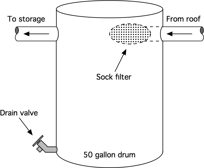
Here, an inflow pipe leading from the gutters penetrates the wall of a 50 gallon plastic drum and terminates with a sock filter (a removable mesh bag) that collects any leaves or larger debris from the water off the roof. The water collects in the barrel until it reaches the level of the outflow pipe, by which time much of the dirt will have washed off the roof.
This is an inexpensive and efficient design that is easy to fabricate. Its disadvantages are that the water in the barrel must be drained after each rainfall and the sock filter cleaned frequently.
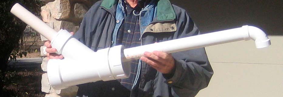
The other design we evaluated was the vortex filter made by WISY, a German manufacturer. This device consists of a vertical cylindrical body with a tangentially positioned 4" inflow pipe near the top, a 4" outflow pipe near the bottom, and a 6" wastewater discharge pipe below that. These can be seen in the drawing and the left-hand photo below. The right-hand photo shows the filter itself, which consists of an open-ended cylinder made of two layers of precisely engineered stainless steel mesh.
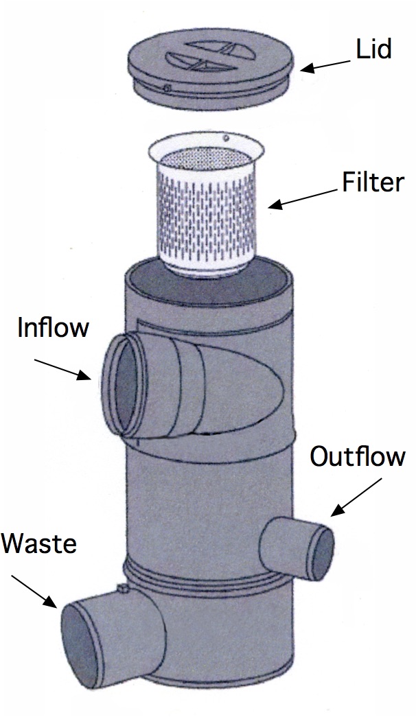
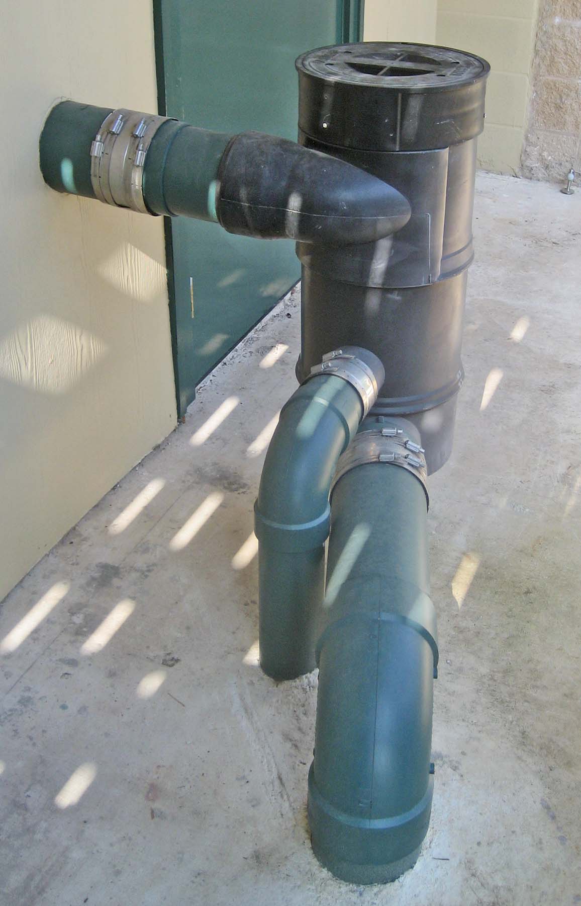
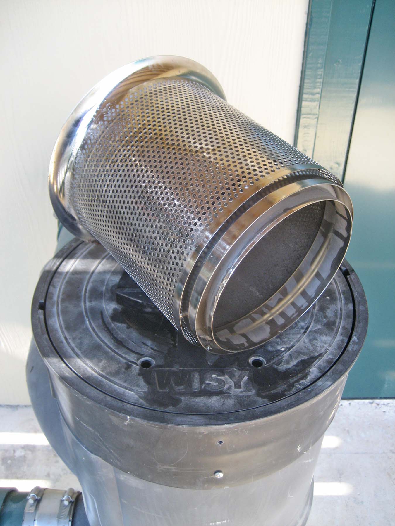
The filter is positioned inside the body where its inner screen comes in contact with the vortex of water injected from the tangential inflow pipe. Surface tension pulls water through the filter and into the outflow pipe. Particulate matter and debris drop through the bottom of the filter and are washed into the wastewater pipe.
We chose two WISY devices (Model WFF 150) because they are self-cleaning and require no regular maintenance other than quarterly washing of the filters in our dishwasher.
The disadvantages of the WISY unit are that it is expensive (in the $600 - $700 range), and that it is not efficient – that is, a relatively high proportion of water is lost through the wastewater discharge. Efficiency is inversely related to rainfall intensity, as can be seen from the graph below (from a WISY brochure):

In practice, efficiency of a working system is difficult to measure since it varies with rainfall intensity, but our impression is that the graph presents an optimistic view – our guess is that we collect only about 70% of the rain that falls on our roof. This leaves us with the conclusion that if your system and pocketbook are robust enough to tolerate it, WISYs are an obvious choice; if they are not, roof washers are probably the way to go.
Tanks
It was important to have our storage tanks located so that their tops would be at a lower elevation than the filter outflow pipes, assuring that water would flow to the tanks from the force of gravity alone – we did not wish to depend on a pump in the case of power failure during a storm. Further, for practical and esthetic reasons, we wanted the tank site to be compact, and we wished to remove as few trees as possible. These considerations set constraints on the number and size of tanks that could be placed on the site.
In the recent past, most rainwater harvest systems in the United States have used above-ground storage tanks made of fiberglass or HDPE plastic. The largest of readily available tanks has a capacity of about 10,000 gallons. Their diameter of 12 feet was acceptable, but their height of about 14 feet exceeded our gravity flow requirements. Smaller tanks might have satisfied the elevation requirement, but more of them would have been required, increasing the area of the site required to hold them.
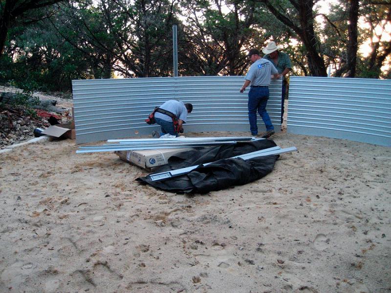
We settled on a pair of 20,000 gallon tanks made by Bluescope Water, an Australian firm. These tanks consist of walls and roof made of sheet steel, inside of which is a heavy flexible plastic liner – much like the construction of an above-ground swimming pool.
They are shipped broken down in a container that fits easily in the bed of a pickup truck (left-hand photo below), and they require only a level bed of sand as a base (right-hand photo).

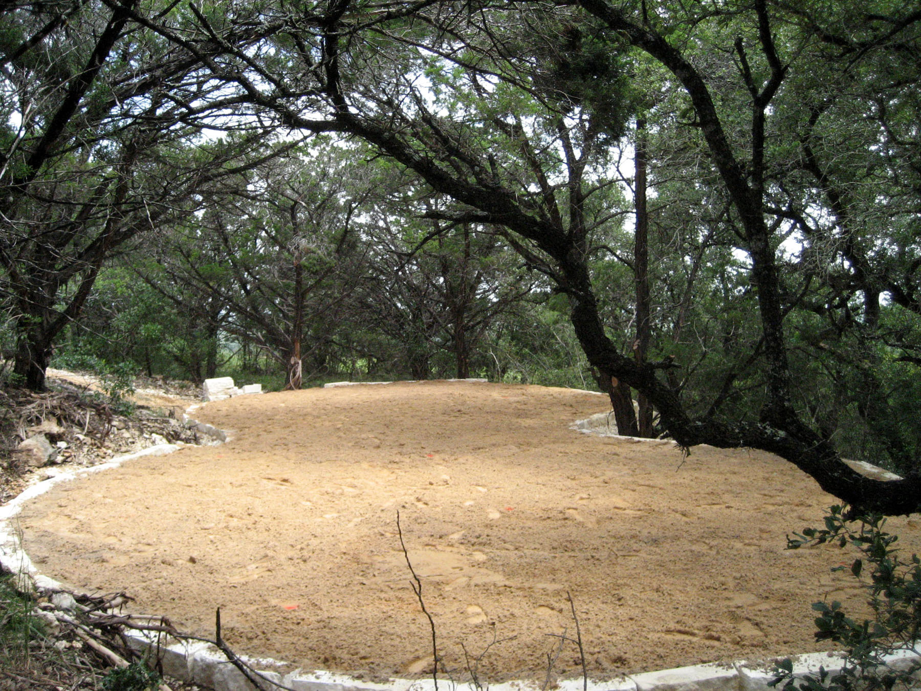
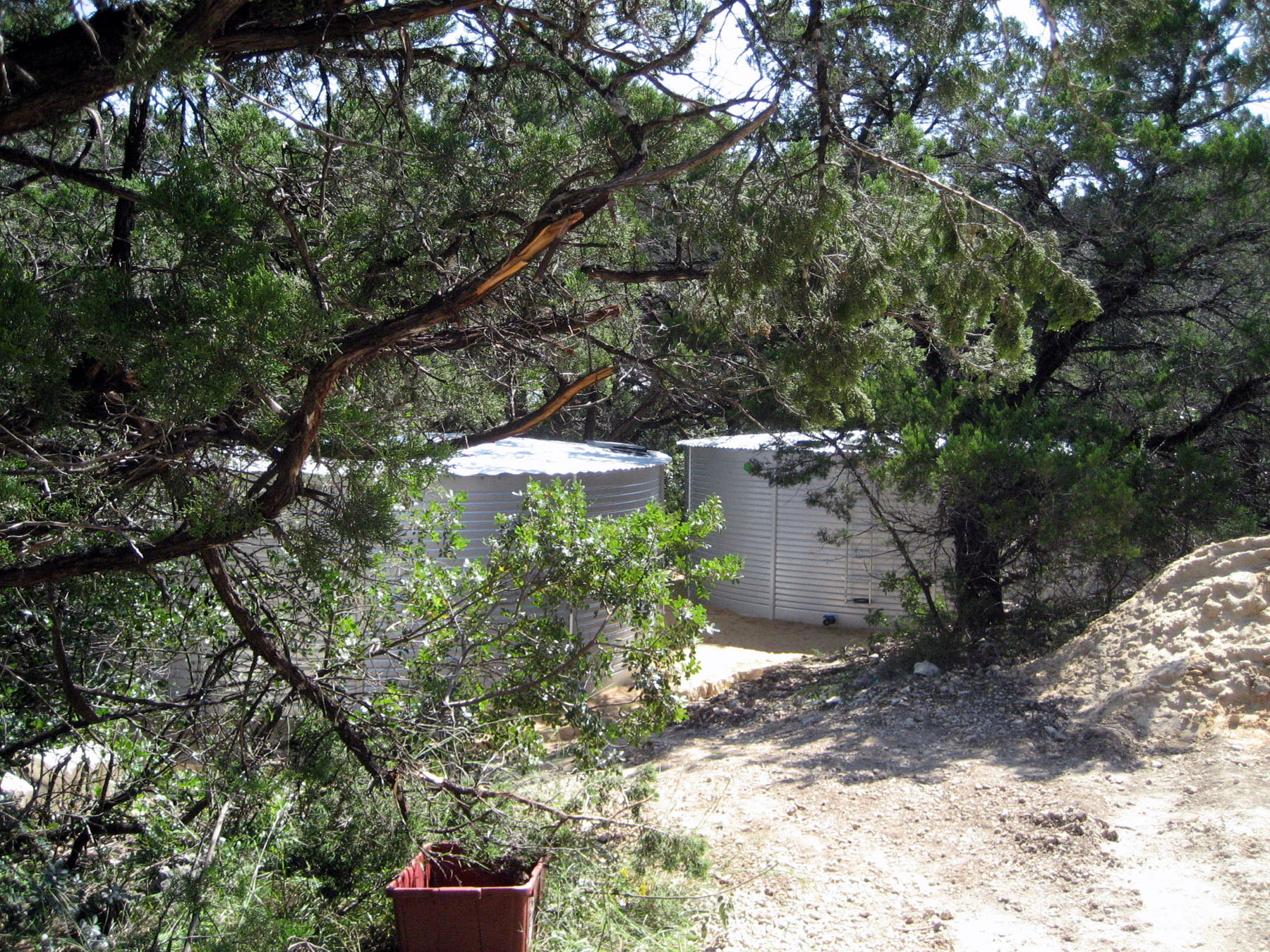
Furthermore, the pieces can be hand carried to the site over a narrow path which results in minimal disturbance to the landscape (left-hand photo below). The tanks fit unobtrusively into the site (right-hand photo), and their seven foot height is low enough to assure gravity flow from the house.
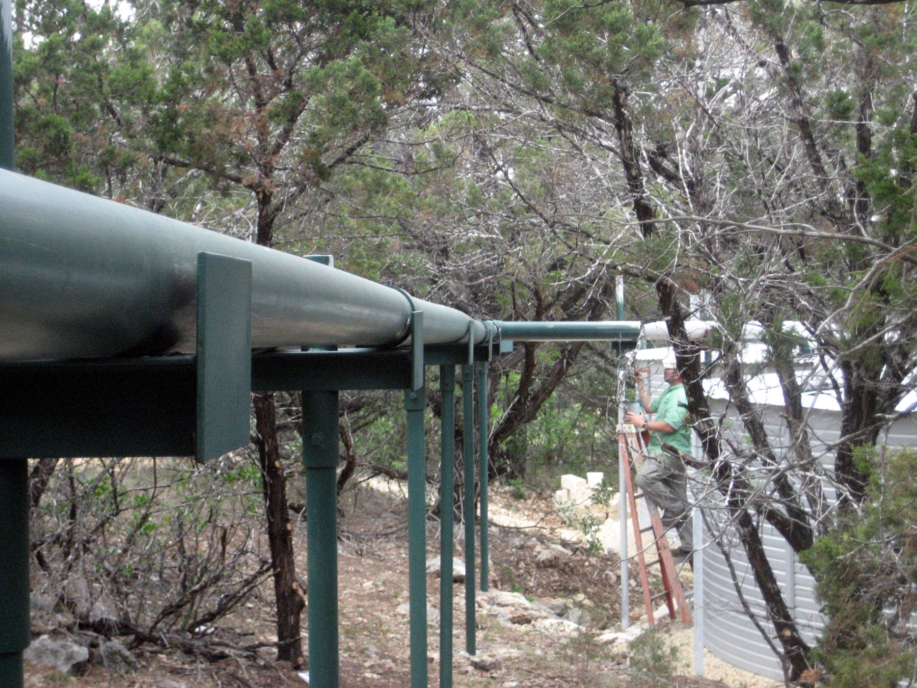
Aqueduct
The tanks are located more than 100 feet from the filter outflow pipes. To prevent stagnation and reduce the accumulation of biofilm, it was important to keep the piping straight, with no dips or low spots that could trap water. To accomplish this, we built a connecting aqueduct consisting of two 4-inch PVC pipes, supported about every 10 feet by steel posts set firmly in the ground.
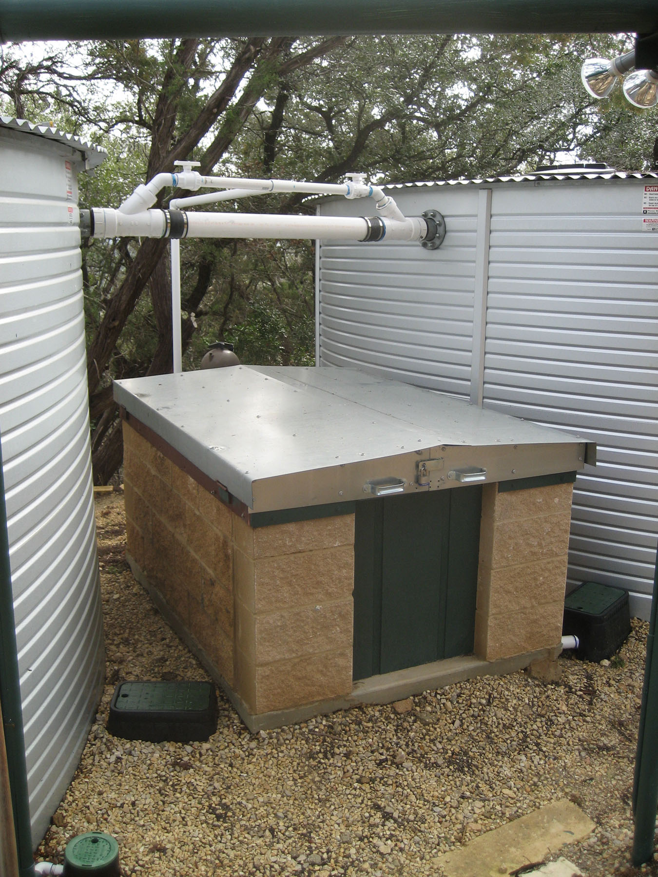
Pump House
A small pump house was built between the two tanks (left-hand photo below). The pump house is just large enough to contain two pumps, one for water supply to the house, and the other powering an external circulating filter. Note the 4" PVC pipe connecting the two tanks above the pump house. This pipe serves two purposes. One is to assure that both tanks reach overflow levels at the same time in a heavy rainfall. The other is to serve as a connection for circulation filter piping.
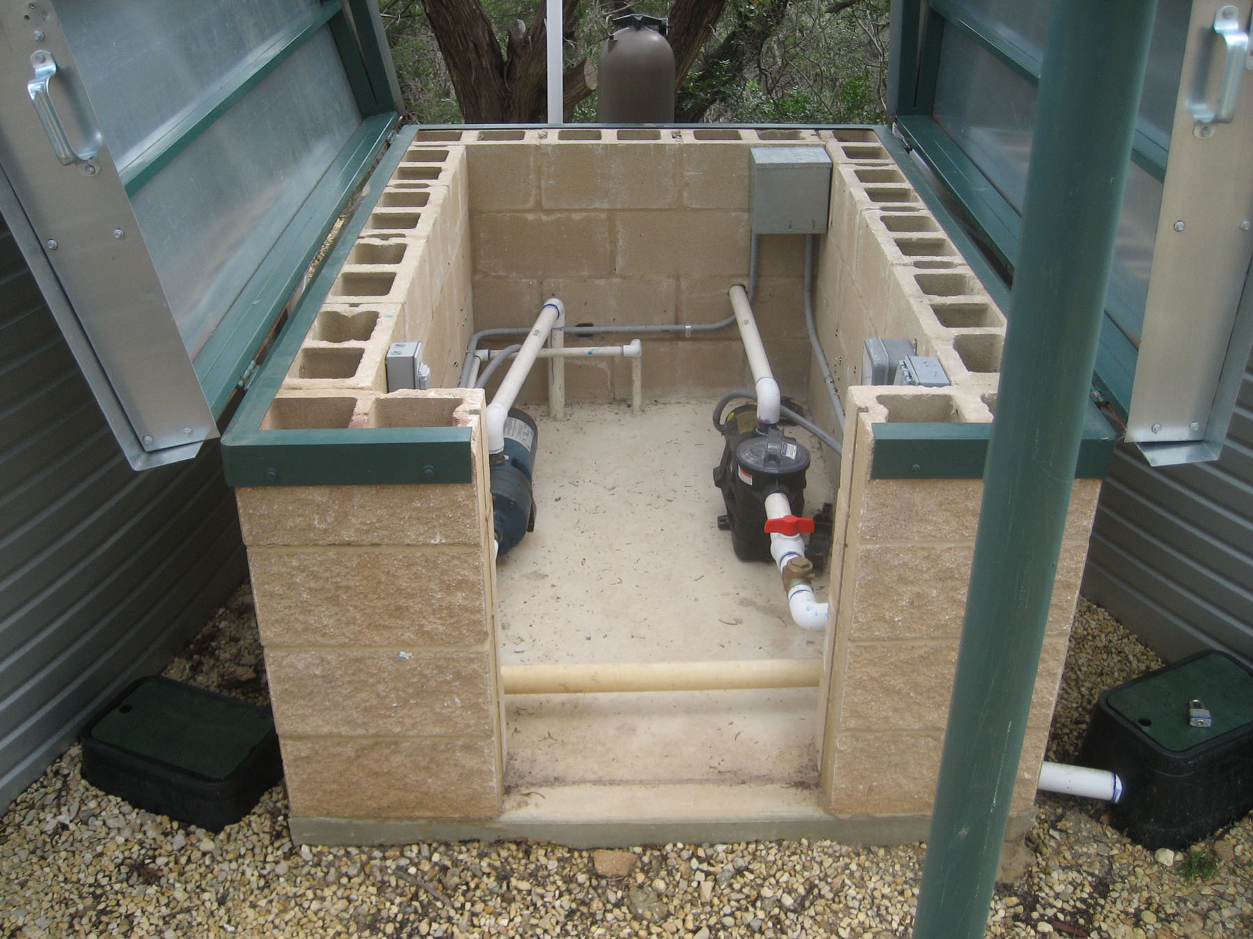
The center photo shows the interior with roof panels and front hatch in open position. Water leaves each tank from an outlet at its bottom and is piped up through the floor of the pump house. Tank cutoff valve boxes can be seen at the bottom of each tank on either side of the pump house.
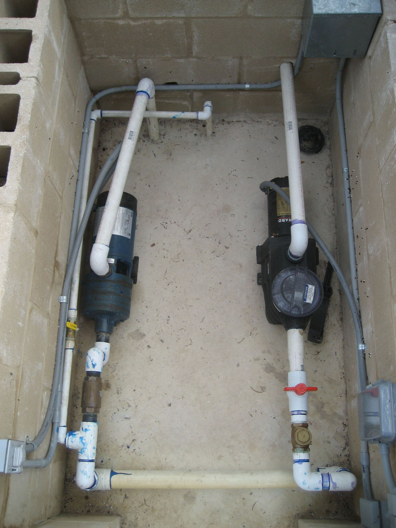
The right-hand photo shows the interior from above. Pipes coming up through the floor are connected to the pumps, but are also connected through the horizontal pipe at the bottom of the photo. This pipe in effect connects the two tanks, assuring that they always contain the same amount of water. The pipe rising from the the top of the pump on the left goes down through the floor to an underground supply line leading to the pressure tank in the garage. The right-hand pump supplies the circulating filter. The very small pipe (3/4") running along the left-hand and back walls connects to the external tank water level gauge.
Circulating Filter
The circulating filter is an ordinary 20 micron swimming pool cartridge assembly (left-hand photo below).
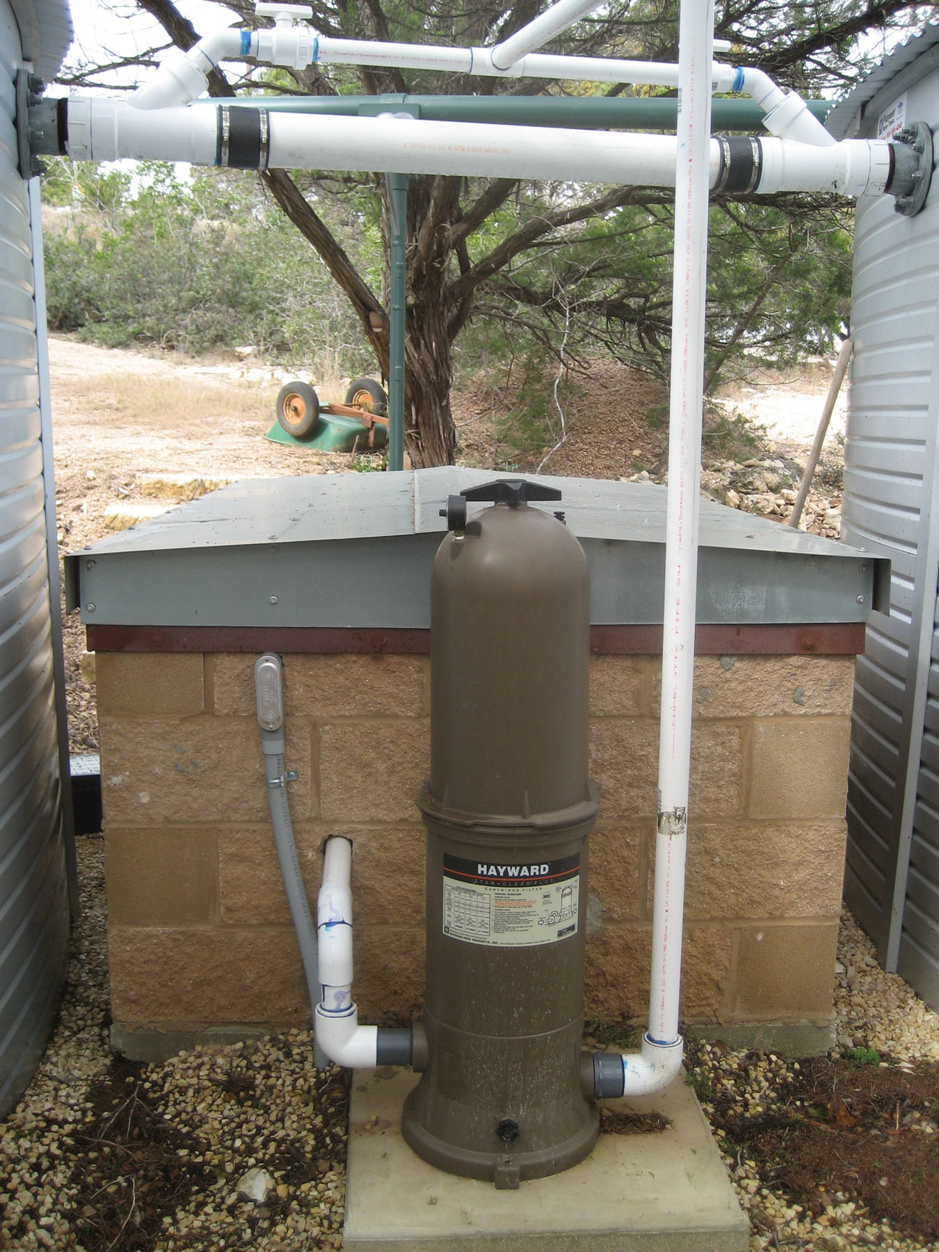
Water is pumped from the tank supply pipes in the pump house, through the filter, and back into the top of each tank through a fitting on the overflow equalizing pipe. Details of the fitting can be seen in the right-hand photo: the smaller pipe projects through the larger 4" wye and into the tank where the ell at the end directs the pumped water downward, keeping it from the hitting the wall of the tank.
Normally, water is pumped equally into both tanks. But the two valves on the smaller pipe adjacent to the fittings can be set so as to direct flow into a single tank. In conjunction with settings of the tank outlet cutoff valves, this makes it possible to transfer water from one tank to the other for cleaning or repair.
Tank Water Level Gauge
The tank water level gauge consists of a piece of transparent Tygon tubing in a rigid case running vertically up the outside of one of the tanks.
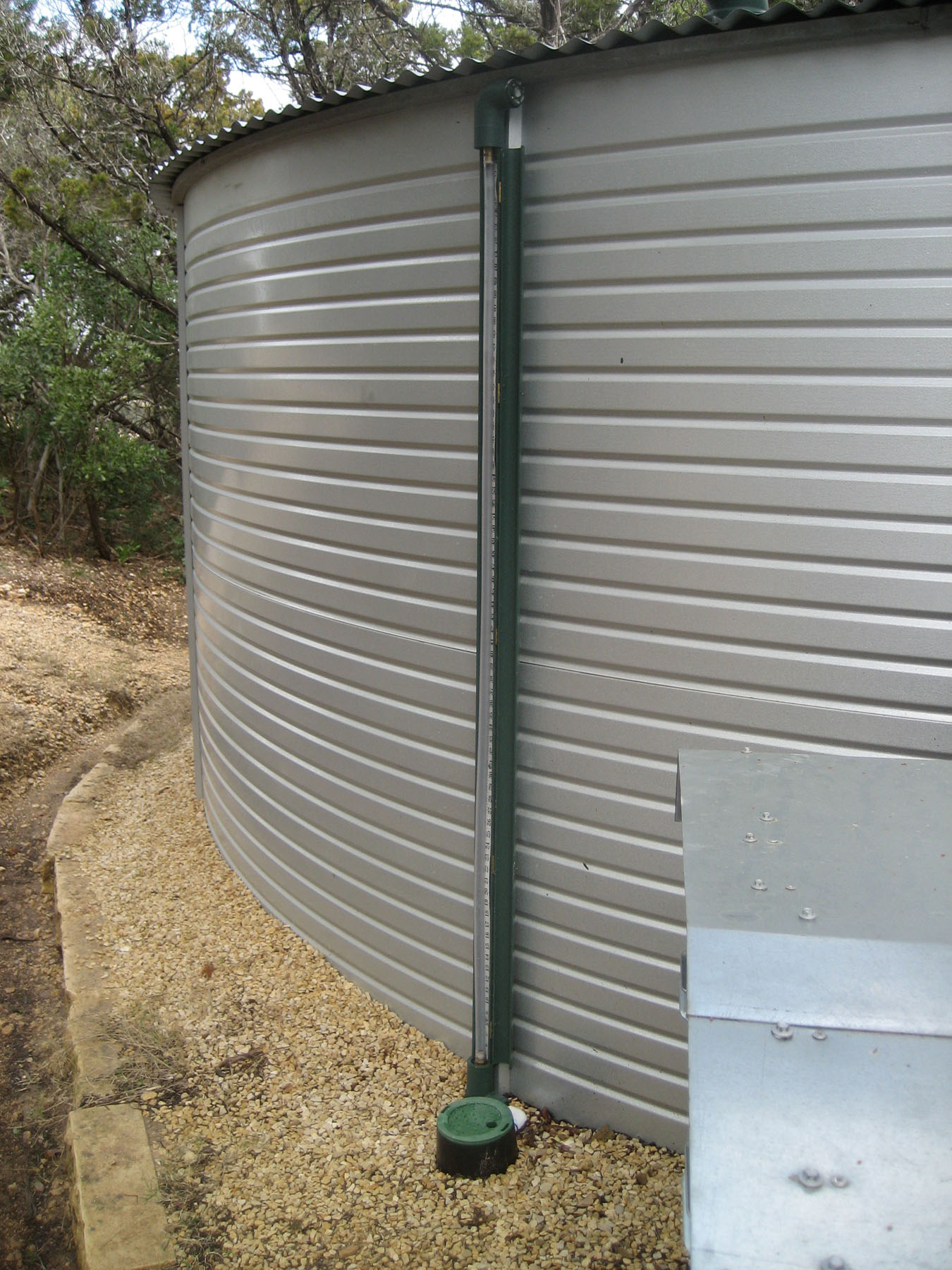
When a valve is opened in the pump house, water in the gauge rises to the level in the tanks. A drain valve in a protective box at the foot of the case empties the gauge. Details of the gauge and its construction may be seen in the following link: Details of the Tank Water Level Gauge.
Drinking Water Treatment
The underground supply pipe from the pump house leads to a pressure tank and filtration/disinfecting system in the garage. All water from the tanks first goes through a 20-micron filter to eliminate any relatively large suspended particles. This water then goes without further treatment to the toilets and hose bibs, and to the purifying equipment where water flows first through a 5-micron sediment filter, then a 5-micron carbon block filter, and finally through an ultra-violet sterilizer. We keep track of both potable and non-potable usage with two water meters, and we measure water pressure before and after the filters so that we know when to change cartridges.
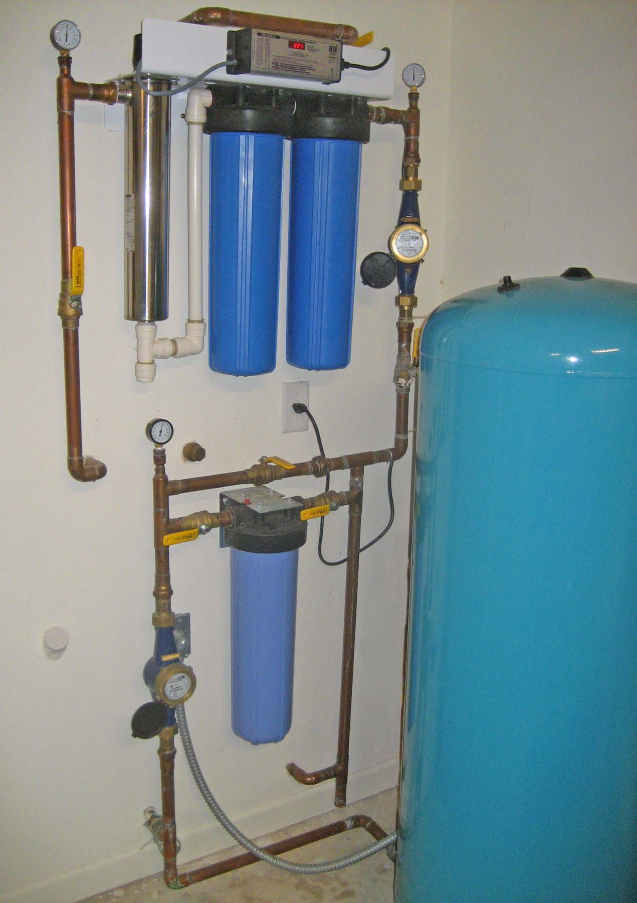
A detailed description of the equipment can be seen here.
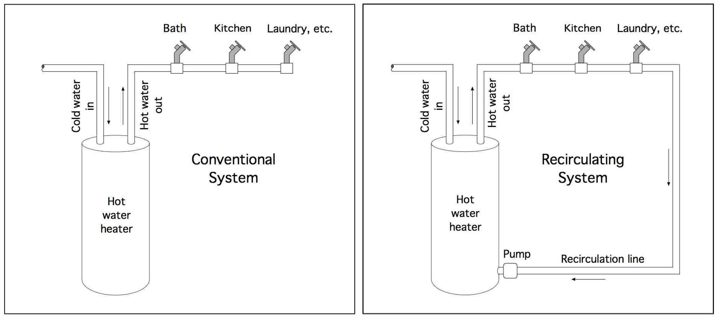
Hot Water Recirculation
As mentioned on the DATA COLLECTION and PLANNING page, we found that a considerable amount of water was wasted when running a faucet until it flowed hot. To eliminate this waste, a recirculating loop and small pump was installed in our hot water plumbing. The pump (on a timer) runs constantly during waking hours, preventing the water in the hot water line from cooling off. With this system, hot water runs from hot water faucets in a few seconds rather than minutes, saving many gallons each day.
The diagrams below illustrate the difference between a conventional, and a recirculating system: